はじめに
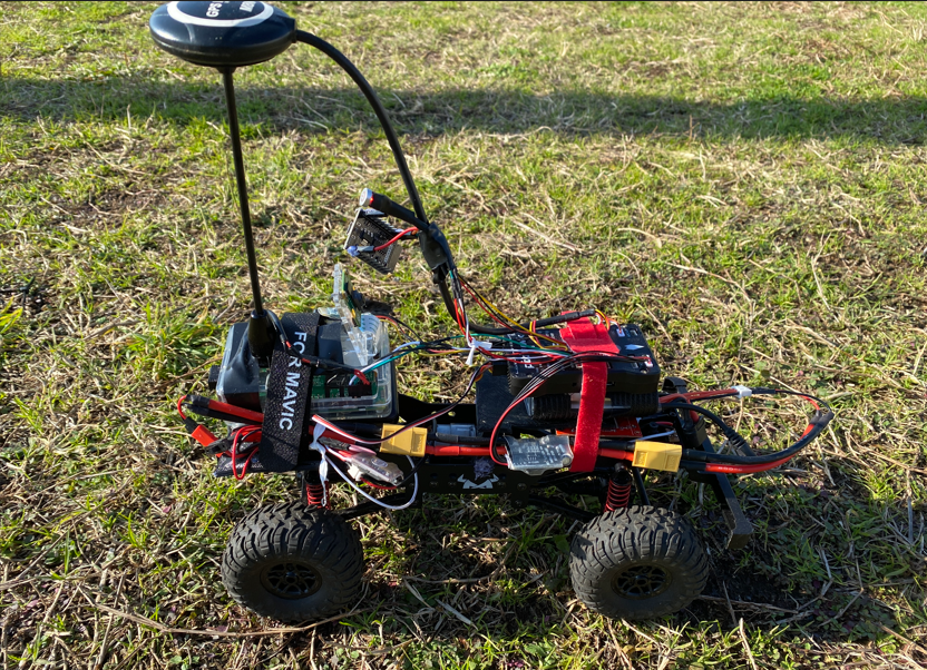
本記事では ArduinoによるFPVラジコン製作を振り返ります。
前記事:ArudinoによるFPVラジコンカーの製作
これまでの開発で得た回路構成やスケッチを整理し、後から読んでも同じ構成で再現できるよう、備忘録を兼ねてハード・ソフト両面の要点をまとめていきます。
今回の開発ではかなりの部分で生成AIの力を活用しました。プログラム作成、記事の構成、体裁を整えたり、ほんとイメージを伝えるだけで完成度の高いテンプレートを生成してくれます。あとは追記、修正していくだけ。生産性爆上がり、すごい世の中になりました。
システム概要(Arduinoラジコン)
システム構成
Arduinoを使ったFPVラジコンカーの全体構成です。
送信機・受信機・ヘッドトラッキングユニットの3ブロックで構成されます。
マイコンの仕様は下記参照ください。
UNO R3 | Arduino Documentation
Nano | Arduino Documentation
使用部品一覧
| 種別 | 名称 | 数量 | 備考 |
|---|---|---|---|
| ベース車体 | DEERC MN99S | 1 | 1/12スケール |
| マイコン | Arduino Uno R3 | 2 | 送信機・受信機用 |
| マイコン | Arduino Nano | 1 | ヘッドトラッキング用 |
| 通信モジュール | nRF24L01 | 3 | 無線通信(2.4GHz) |
| ジャイロセンサー | MPU6050 | 1 | 頭部動作の加速度・角速度検出 |
| 地磁気センサー | HMC5883L | 1 | 磁場を検出(将来向け) |
| モータードライバ | L298N | 1 | DCモーター制御 |
| サーボモーター | SG90×2 | 1組 | カメラ用2軸ジンバル制御 |
| ジョイスティック | VKLSVANモジュール | 2 | 操作入力用 |
| VTX送信機 | 5.8GHzタイプ | 1 | FPV映像送信用 |
ハードウェア構成詳細
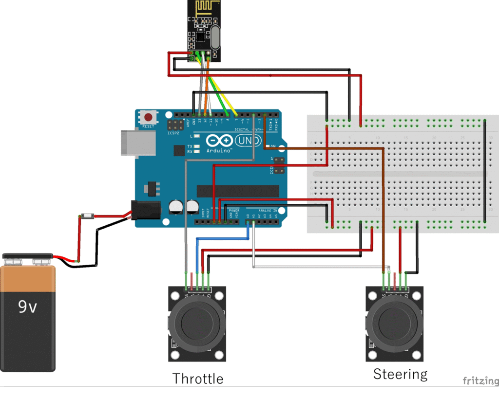
送信機(Transmitter)
Arduino Unoをベースに、ジョイスティック操作の読み取り、およびヘッドトラッキングセンサーからのデータを受信し、nRF24L01を通して車体側の受信機に送信します。
- ジョイスティック接続
- A1: Y(右スティックがステアリング)
- A0: X (左スティックがスロットル)
- SW: D2 (右スティックSWで動作モード切替 :アイドル/モータ・ステアリング/カメラ制御を順次オン、最後までいったらアイドルに戻る)
- SW: D4 (左スティックSWでカメラ位置リセット:センターに戻る)
- nRF24L01接続
- CE: D7
- CSN: D8
- MOSI: D11(SPIライブラリにより自動設定)
- MISO: D12(SPIライブラリにより自動設定)
- SCK: D13(SPIライブラリにより自動設定)
- 構成図
受信機(Receiver)
車体側では、L298Nを通じてモータを駆動し、サーボ(ステアリング、カメラ)を制御します。
- モータ制御
- IN1(3): D4 → 1chではトルク弱いので並列接続して使用
- IN2(4): D2 → 同様
- ENB: D6(PWM)
- 出力端子:OUT3/OUT4 → モータ接続
- ステアリングサーボ
- ピン D3 に接続(Servoライブラリ制御)
- カメラ制御サーボ
- Pitch: D5
- Yaw: D9
- nRF24L01接続
- CE: D7
- CSN: D8
- MOSI: D11(SPIライブラリにより自動設定)
- MISO: D12(SPIライブラリにより自動設定)
- SCK: D13(SPIライブラリにより自動設定)
- 構成図

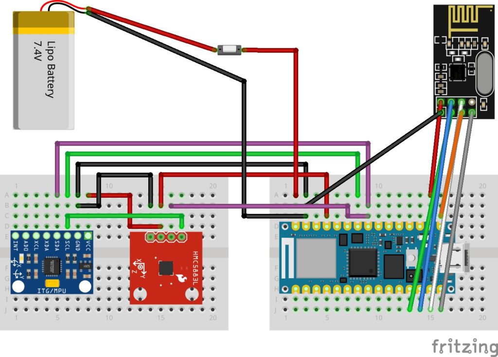
ヘッドトラッキングユニット
Arduino Nano+MPU6050で操作者の頭部の傾きを取得し、Yaw/PitchデータをnRF24L01経由で送信機(ジョイスティックコントーローラ)へ送信します。
(地磁気センサーHTC5883Lは将来に向けて接続のみ)
- MPU6050接続:SDA→A4, SCL→A5
- HTC5883L接続:SDA→A4, SCL→A5
- nRF24接続:CE→D9, CSN→D10
ソフトウェア概要
本システムでは、3種類のスケッチを組み合わせて動作します。
| スケッチ名 | 機能 | 主なハードウェア |
|---|---|---|
| transmitter.ino | ジョイスティック入力送信 | Arduino Uno(送信機側) |
| receiver.ino | モータ+サーボ制御受信 | Arduino Uno(車体側) |
| head_tracking.ino | ヘッド角度を取得し送信 | Arduino Nano+MPU6050 |
/*
  Transmitter
  -------------------------------------------
  - Inputs: 2-axis joystick (steering/throttle) + 2 buttons (right/left)
  - IMU:    MPU6050 (wired I2C)
  - Radio:  nRF24L01
  - Packet: int16_t[6] = {X, Y, BTN_R, YAW, PITCH, BTN_L}

  Notes:
  * Keep TX and RX data types/length in sync on the receiver side.
  * Button logic uses INPUT_PULLUP (pressed = 1, released = 0).
*/

#include <Wire.h>
#include <SPI.h>
#include <nRF24L01.h>
#include <RF24.h>
#include <MPU6050.h>
#include <math.h>  // for atan2, sqrt, M_PI

// ---------------------- Pins ----------------------
constexpr uint8_t JOY_X_PIN       = A1; // Steering
constexpr uint8_t JOY_Y_PIN       = A0; // Throttle
constexpr uint8_t BTN_RIGHT_PIN   = 2;  // Joystick right button
constexpr uint8_t BTN_LEFT_PIN    = 4;  // Joystick left button

// ---------------------- Radio ---------------------
RF24 radio(7, 8);                 // CE, CSN
const uint64_t PIPE_TX  = 0xF0F0F0E1LL; // Transmit pipe (to receiver)
const uint64_t PIPE_IMU = 0xF0F0F0E2LL; // Wireless IMU pipe (from remote IMU)

// ---------------------- IMU -----------------------
MPU6050 mpu;

// ---------------------- Data Packet ---------------
enum {
  IDX_X = 0,     // Joystick X (steering)
  IDX_Y = 1,     // Joystick Y (throttle)
  IDX_BTN_R = 2, // Right button (1=pressed)
  IDX_YAW = 3,   // Yaw (deg, int)
  IDX_PITCH = 4, // Pitch (deg, int)
  IDX_BTN_L = 5  // Left button (1=pressed)
};

int16_t joystickData[6] = {0};   // TX payload
int16_t mpu6050Data[2]  = {0};   // Wireless IMU {yaw, pitch}

// ---------------------- Timing --------------------
unsigned long loopStartMs = 0;
const float timeStep = 0.02f;     // 50 ms

// ---------------------- State ---------------------
float yawDeg   = 0.0f;
float pitchDeg = 0.0f;

int attempts = 0;
const int MAX_ATTEMPTS = 10;
bool useLocalIMU = false;

// --------------------------------------------------
// setup
// --------------------------------------------------
void setup() {
  Serial.begin(9600);

  // Buttons with pull-ups (pressed = LOW)
  pinMode(BTN_RIGHT_PIN, INPUT_PULLUP);
  pinMode(BTN_LEFT_PIN,  INPUT_PULLUP);

  // Radio init
  radio.begin();
  radio.setPALevel(RF24_PA_HIGH);
  radio.setDataRate(RF24_1MBPS);
  radio.setAutoAck(true);
  radio.setRetries(5, 15);
  radio.openWritingPipe(PIPE_TX);
  radio.stopListening(); // default to TX mode

  // Try local IMU (via I2C)
  while (!mpu.begin(MPU6050_SCALE_2000DPS, MPU6050_RANGE_2G)) {
    Serial.println(F("MPU6050 not found, check wiring..."));
    delay(500);
    attempts++;
    if (attempts >= MAX_ATTEMPTS) {
      Serial.println(F("Failed to init MPU6050 after 10 attempts. Using wireless IMU."));
      break;
    }
  }

  if (attempts < MAX_ATTEMPTS) {
    // Local IMU OK
    mpu.calibrateGyro();
    mpu.setThreshold(3);     // 0 to disable threshold; 3 is a reasonable default
    useLocalIMU = true;
    Serial.println(F("Local MPU6050 initialized."));
  } else {
    // Fallback: receive IMU data wirelessly on pipe #1
    radio.openReadingPipe(1, PIPE_IMU);
    radio.startListening();
    useLocalIMU = false;
    Serial.println(F("Wireless IMU mode (listening on pipe #1)."));
  }
}

// --------------------------------------------------
// loop
// --------------------------------------------------
void loop() {
  loopStartMs = millis();

  // ----- Read joystick -----
  joystickData[IDX_X] = analogRead(JOY_X_PIN); // 0..1023
  joystickData[IDX_Y] = analogRead(JOY_Y_PIN); // 0..1023

  // Normalize buttons to 1=pressed, 0=released
  joystickData[IDX_BTN_R] = (digitalRead(BTN_RIGHT_PIN) == LOW) ? 1 : 0;
  joystickData[IDX_BTN_L] = (digitalRead(BTN_LEFT_PIN)  == LOW) ? 1 : 0;

  // ----- IMU: local or wireless -----
  if (useLocalIMU) {
    // Local wired IMU
    Vector g = mpu.readNormalizeGyro();   // dps
    Vector a = mpu.readNormalizeAccel();  // g

    // Integrate yaw (Z-axis)
    yawDeg += g.ZAxis * timeStep;

    // Wrap yaw to [-180, 180]
    if (yawDeg > 180.0f)  yawDeg -= 360.0f;
    if (yawDeg < -180.0f) yawDeg += 360.0f;

    // Pitch from accelerometer (degrees)
    pitchDeg = -(atan2(a.XAxis, sqrt(a.YAxis * a.YAxis + a.ZAxis * a.ZAxis)) * 180.0f) / M_PI;

    // Cast to int16 for TX
    joystickData[IDX_YAW]   = (int16_t)(-yawDeg); // keep sign, invert if needed for your frame
    joystickData[IDX_PITCH] = (int16_t)( pitchDeg);
  } else {
    // Wireless IMU mode: read {yaw, pitch} if available
    if (radio.available()) {
      radio.read(mpu6050Data, sizeof(mpu6050Data));
      if (mpu6050Data[0] != 0 || mpu6050Data[1] != 0) {
        joystickData[IDX_YAW]   = mpu6050Data[0];
        joystickData[IDX_PITCH] = mpu6050Data[1];
      } else {
        joystickData[IDX_YAW]   = 0;
        joystickData[IDX_PITCH] = 0;
      }
    }
  }

  // ----- Transmit packet -----
  // Briefly stop listening (if we were in wireless-IMU mode) to send the TX frame.
  radio.stopListening();
  (void)radio.write(joystickData, sizeof(joystickData));
  if (!useLocalIMU) radio.startListening(); // resume listening only in wireless-IMU mode

  // ----- Debug prints -----
  Serial.print(F("Yaw: "));     Serial.print(joystickData[IDX_YAW]);
  Serial.print(F("\tPitch: "));  Serial.print(joystickData[IDX_PITCH]);
  Serial.print(F("\tBtnR: "));   Serial.print(joystickData[IDX_BTN_R]);
  Serial.print(F("\tBtnL: "));   Serial.print(joystickData[IDX_BTN_L]);
  Serial.print(F("\tX: "));      Serial.print(joystickData[IDX_X]);
  Serial.print(F("\tY: "));      Serial.println(joystickData[IDX_Y]);

  // ----- Keep setting ms loop period -----
  long elapsed = (long)(millis() - loopStartMs);
  long remaining = (long)(timeStep * 1000.0f) - elapsed;
  if (remaining > 0) delay((unsigned long)remaining);
}
/*
  Receiver
  -----------------
  - Radio: nRF24L01 (TMRh20 RF24)
  - Packet: int16_t[6] = {X, Y, BTN_R, YAW, PITCH, BTN_L}
  - Steering: ServoTimer2 on pin 3 (pulse width in microseconds)
  - Camera:   ServoTimer2 on pins 9 (Yaw), 5 (Pitch)
  - Motor:    H-bridge (IN1, IN2, ENB PWM)
  - I2C:      Reserved for future use (slave @ 0x08). Currently not used.

  Notes:
  * Types and names are aligned with the transmitter (int16_t and IDX_* enum).
  * RF payload size/type must match the transmitter exactly.
  * Numeric tuning for steering/motor/camera is preserved as provided.
*/

#include <SPI.h>
#include <nRF24L01.h>
#include <RF24.h>
#include <Wire.h>
#include <ServoTimer2.h>

// ---------------------- RF24 ----------------------
RF24 radio(7, 8);                       // CE, CSN
static const uint64_t PIPE_RX = 0xF0F0F0E1LL; // keep as-is (matches your TX)

// ---------------------- Packet layout (aligned) ---
enum {
  IDX_X = 0,     // Joystick X (steering)
  IDX_Y = 1,     // Joystick Y (throttle)
  IDX_BTN_R = 2, // Right button (1=pressed)
  IDX_YAW = 3,   // Yaw (deg, int16)
  IDX_PITCH = 4, // Pitch (deg, int16)
  IDX_BTN_L = 5  // Left button (1=pressed)
};

int16_t joystickData[6] = {0};

// Current control values (I2C may override in future)
volatile int16_t joystickXValue = 0;
volatile int16_t joystickYValue = 0;
int16_t yaw   = 0;
int16_t pitch = 0;

int joystickSWValue    = 0;
int joystickSWValueLft = 1;

// ---------------------- Start state ---------------
volatile int startH = 1;
volatile int startL = 0;
volatile int start  = 0;

// ---------------------- Servos --------------------
ServoTimer2 myservo; // steering
ServoTimer2 servoZ;  // camera yaw
ServoTimer2 servoY;  // camera pitch

// Steering
int pos = 1200;                 // raw reading placeholder
const int SEVO_pin = 3;

// Camera servo pins
int camera_servoZPin = 9;       // yaw
int camera_servoYPin = 5;       // pitch

// ---------------------- DC motor ------------------
const int IN1 = 4; // digital
const int IN2 = 2; // digital
const int ENB = 6; // PWM
int dc_dir = 0, pwm_acc = 0, pwm = 0;

// ---------------------- Steering tuning (keep) ----
int centerMin    = 506;
int centerMax    = 516;
int leftMin      = 2200;
int rightMax     = 1000;
int centerOutput = 1600;
int mappedPos    = 1600;

// ---------------------- I2C (future use) ----------
volatile int16_t receivedDatai2c = 520;
volatile int16_t receivedCmndi2c = 5;

void receiveEvent(int howMany) {
  // Enter override mode
  start = 5;

  // Expect cmd + 2-byte data per frame
  while (Wire.available() >= 3) {
    uint8_t cmd       = Wire.read();
    uint8_t high_byte = Wire.read();
    uint8_t low_byte  = Wire.read();

    receivedCmndi2c = cmd;
    receivedDatai2c = (int16_t)((high_byte << 8) | low_byte);

    // Override X or Y depending on cmd (kept behavior)
    if (cmd == 3 || cmd == 4 || cmd == 6) {
      joystickXValue = receivedDatai2c;
    }
    if (cmd == 1 || cmd == 2 || cmd == 5) {
      joystickYValue = receivedDatai2c;
    }
  }
}

void setup() {
  Serial.begin(9600);

  // -------- RF24 --------
  radio.begin();
  radio.openReadingPipe(1, PIPE_RX);      // keep the tuned address
  radio.setPALevel(RF24_PA_HIGH);
  radio.setDataRate(RF24_1MBPS);          // align with transmitter
  radio.startListening();

  // -------- Motor -------
  pinMode(IN1, OUTPUT);
  pinMode(IN2, OUTPUT);
  pinMode(ENB, OUTPUT);

  // -------- Servos ------
  myservo.attach(SEVO_pin);
  servoZ.attach(camera_servoZPin);
  servoY.attach(camera_servoYPin);

  // -------- I2C (future) -
  Wire.begin(0x08);               // I2C slave address
  Wire.onReceive(receiveEvent);   // Registered ISR (currently unused)
}

void loop() {
  // -------- Read RF24 (latest frame wins) --------
  if (radio.available()) {
    // Flush to latest frame if multiple are queued
    while (radio.available()) {
      radio.read(joystickData, sizeof(joystickData));
    }

    // Update from RF
    joystickXValue    = joystickData[IDX_X];
    joystickYValue    = joystickData[IDX_Y];
    joystickSWValue   = joystickData[IDX_BTN_R];
    joystickSWValueLft= joystickData[IDX_BTN_L];
    yaw               = joystickData[IDX_YAW];
    pitch             = joystickData[IDX_PITCH];

    // Edge detection for start state
    if (joystickSWValue == 1) {
      startH = 1;
    }
    if (startH == 1 && joystickSWValue == 0) {
      startH = 0;
      start += 1;
      if (start > 3) start = 0;
    }
  }

  // -------- Control (kept behaviors & thresholds) --------
  if (start >= 1) {
    // Snapshot to avoid tearing with ISR writes
    int localX = joystickXValue;
    int localY = joystickYValue;

    // Steering mapping (keep your tuning)
    pos = localX;
    if (pos < centerMin) {
      mappedPos = map(pos, 0, centerMin, leftMin, centerOutput);
    } else if (pos > centerMax) {
      mappedPos = map(pos, centerMax + 1, 1023, centerOutput, rightMax);
    } else {
      mappedPos = centerOutput;
    }
    myservo.write(mappedPos);
    delay(15);

    // Motor mapping (keep your thresholds)
    pwm_acc = localY;
    if (pwm_acc > 550) {
      digitalWrite(IN1, HIGH);
      digitalWrite(IN2, LOW);
      pwm = map(pwm_acc, 550, 1023, 0, 255);
      analogWrite(ENB, pwm);
    } else if (pwm_acc < 500) {
      digitalWrite(IN1, LOW);
      digitalWrite(IN2, HIGH);
      pwm = map(pwm_acc, 0, 500, 255, 0);
      analogWrite(ENB, pwm);
    } else {
      digitalWrite(IN1, LOW);
      digitalWrite(IN2, LOW);
      analogWrite(ENB, 0);
    }

    // Camera servos (active for start=2..4)
    if (start >= 2 && start <= 4) {
      int servoZAngle = map((int)yaw,   -90, 90, 2500, 100); // keep as-is
      int servoYAngle = map((int)pitch, -90, 90, 2500, 100); // keep as-is
      servoZ.write(servoZAngle);
      servoY.write(servoYAngle);
    }

    delay(10);
  }

  delay(10);
}
/*
 Head_tracking
  ------------------------------------------------------------------
  Board:   Arduino Nano
  Sensors: MPU6050 (gyro/accel), QMC5883L (mag; optional)
  Radio:   nRF24L01

  Rationale:
    - Some RX servos/logic need a stable neutral (exact zeros) for a short time.
      Latching (0,0) for a few frames guarantees the camera snaps back to the same
      power-on neutral, regardless of sensor orientation at the moment.
*/

#include <Wire.h>
#include <SPI.h>
#include <nRF24L01.h>
#include <RF24.h>
#include <MadgwickAHRS.h>
#include <MPU6050.h>
#include <QMC5883LCompass.h>
#include <math.h>
#include <stdint.h>

// ---------------------- RF24 setup ----------------------
RF24 radio(9, 10);                            // CE, CSN
static const uint64_t PIPE_TX = 0xF0F0F0E2LL; // write: to TX (TX listens here)
static const uint64_t PIPE_RX = 0xF0F0F0E1LL; // read : from TX (joystickData)

// ---------------------- Joystick frame indices ----------
enum {
  IDX_X = 0,      // (unused here)
  IDX_Y = 1,      // (unused here)
  IDX_BTN_R = 2,  // Right button (unused here)
  IDX_YAW = 3,    // Yaw (to be filled by TX from our payload)
  IDX_PITCH = 4,  // Pitch (to be filled by TX from our payload)
  IDX_BTN_L = 5   // Left button (Active-Low: 0 = pressed)
};

// Joystick frame coming from TX (we only read buttons)
int16_t joystickData[6] = {0};

// Outgoing payload to TX
int16_t mpu6050Data[2] = {0, 0};  // {yawDeg, pitchDeg}

// ---------------------- IMU / Filter --------------------
MPU6050 mpu;
QMC5883LCompass compass;                     // optional (kept for compatibility)
Madgwick filter;

constexpr float SAMPLE_RATE_HZ = 100.0f;     // filter internal rate
constexpr float LOOP_DT        = 0.02f;       // 50 ms loop interval

// Raw normalized sensor vectors
Vector normGyro, normAccel;

// Integrated yaw (deg) from gyro Z; pitch from accel tilt
float gYawDeg   = 0.0f;
float pitchDeg  = 0.0f;

// ---------------------- Button handling -----------------
constexpr unsigned long DEBOUNCE_MS = 150;
unsigned long lastLeftEdgeMs = 0;
bool prevLeftPressed = false;         // previous LEFT pressed state (Active-Low)
static inline bool isPressedActiveLow(int16_t v) { return v == 0; } // 0 = pressed

// ---------------------- Hard-center latch ----------------
/*
  When LEFT is pressed, we want to force the exact neutral (0,0)
  for several loop ticks so RX surely snaps back to power-on center.
*/
constexpr int CENTER_HOLD_TICKS =2;   // ~0.4s at 200ms/tick; adjust to taste
int centerHoldCountdown = 0;

// ---------------------- Setup ---------------------------
void setup() {
  Serial.begin(9600);
  Wire.begin();

  // --- Radio init ---
  radio.begin();
  radio.setPALevel(RF24_PA_HIGH);
  radio.setDataRate(RF24_1MBPS);
  radio.setAutoAck(true);
  radio.setRetries(5, 15);
  radio.openWritingPipe(PIPE_TX);
  radio.openReadingPipe(1, PIPE_RX);
  radio.startListening();

  // --- MPU6050 init ---
  int attempts = 0;
  const int MAX_ATTEMPTS = 10;
  while (!mpu.begin(MPU6050_SCALE_2000DPS, MPU6050_RANGE_2G)) {
    Serial.println(F("MPU6050 not found, check wiring..."));
    delay(500);
    attempts++;
    if (attempts >= MAX_ATTEMPTS) {
      Serial.println(F("Proceeding without full MPU init (fallback)."));
      break;
    }
  }
  if (attempts < MAX_ATTEMPTS) {
    mpu.calibrateGyro();
    mpu.setThreshold(3);
  }

  // --- Compass (optional; not strictly used here) ---
  compass.init();
  compass.setCalibration(0, 0, 0, 0, 0, 0);

  // --- Filter init ---
  filter.begin(SAMPLE_RATE_HZ);
}

// ---------------------- Main loop -----------------------
void loop() {
  unsigned long loopStartMs = millis();

  // --- Read IMU ---
  normGyro  = mpu.readNormalizeGyro();    // dps (deg/sec)
  normAccel = mpu.readNormalizeAccel();   // g

  // Integrate yaw around Z using fixed DT
  gYawDeg += normGyro.ZAxis * LOOP_DT;

  // Keep yaw within [-180, 180] range (optional but keeps numbers)
  if (gYawDeg > 180.0f)  gYawDeg -= 360.0f;
  if (gYawDeg < -180.0f) gYawDeg += 360.0f;

  // Pitch from accelerometer tilt (deg)
  pitchDeg = -(atan2(
                normAccel.XAxis,
                sqrt(normAccel.YAxis * normAccel.YAxis + normAccel.ZAxis * normAccel.ZAxis)
              ) * 180.0f) / M_PI;

  // --- Read joystick frame from TX to get LEFT button state ---
  if (radio.available()) {
    radio.read(joystickData, sizeof(joystickData));
  }
  bool leftPressed = isPressedActiveLow(joystickData[IDX_BTN_L]); // 0 = pressed

  // --- LEFT button falling edge (1 -> 0): hard-center latch start ---
  if (leftPressed && !prevLeftPressed) {
    if (millis() - lastLeftEdgeMs > DEBOUNCE_MS) {
      // Reset algorithm state to define "now" as zero
      gYawDeg = 0.0f;
      filter.begin(SAMPLE_RATE_HZ);   // re-seed filter
      // Force exact neutral for several ticks so RX surely centers
      centerHoldCountdown = CENTER_HOLD_TICKS;
      lastLeftEdgeMs = millis();
    }
  }
  prevLeftPressed = leftPressed;

  // --- Compose outputs ---
  int16_t yawOutDeg;
  int16_t pitchOutDeg;

  if (centerHoldCountdown > 0) {
    // Hard-center latch: force (0,0) to RX
    yawOutDeg   = 0;
    pitchOutDeg = 0;
    centerHoldCountdown--;
  } else {
    //Normal tracking (unchanged): RX expects -gYawDeg for yaw
    yawOutDeg   = (int16_t)lrintf(-gYawDeg);
    pitchOutDeg = (int16_t)lrintf(pitchDeg);
  }

  mpu6050Data[0] = yawOutDeg;    // yaw
  mpu6050Data[1] = pitchOutDeg;  // pitch

  // --- Send payload to TX (2 x int16_t) ---
  radio.stopListening();
  (void)radio.write(mpu6050Data, sizeof(mpu6050Data));
  radio.startListening();

  // --- Debug (optional) ---
  // Serial.print(F("gYawDeg="));  Serial.print(gYawDeg);
  // Serial.print(F("  pitchDeg=")); Serial.print(pitchDeg);
  // Serial.print(F("  yawOut="));  Serial.print(yawOutDeg);
  // Serial.print(F("  L="));       Serial.print(leftPressed ? 1 : 0);
  // Serial.print(F("  latch="));   Serial.println(centerHoldCountdown);

  // --- Maintain ~200 ms cadence ---
  long elapsed = (long)(millis() - loopStartMs);
  long remaining = (long)(LOOP_DT * 1000.0f) - elapsed;
  if (remaining > 0) delay((unsigned long)remaining);
}
ご参考
モータをESC制御(Itisyou社製の30A)に変更した版です。D6(PWM)を利用します。
LP298Nではトルクが足りなくちょっとした段差が乗り越えられなかったので、こちらにしたら頑張ってくれました。受信機のソースコードです。
/*
  RC Rover Receiver <ESC版>
  -----------------
  - Radio: nRF24L01 (TMRh20 RF24)
  - Packet: int16_t[6] = {X, Y, BTN_R, YAW, PITCH, BTN_L}
  - Steering: ServoTimer2 on pin 3 (pulse width in microseconds)
  - Camera:   ServoTimer2 on pins 9 (Yaw), 5 (Pitch)
  - Motor:
      [OLD] H-bridge (IN1, IN2, ENB PWM)
      [NEW] Brushed ESC on ENB(D6) via ServoTimer2 (50Hz, 1000-2000us)
  - I2C:      Reserved for future use (slave @ 0x08). Currently not used.

  Notes:
  * L298N時代のモータ制御コードはコメントアウトで残してあります。
  * モータ制御以外のロジック/パラメータは変更していません。
*/

#include <SPI.h>
#include <nRF24L01.h>
#include <RF24.h>
#include <Wire.h>
#include <ServoTimer2.h>

// ---------------------- RF24 ----------------------
RF24 radio(7, 8);                       // CE, CSN
static const uint64_t PIPE_RX = 0xF0F0F0E1LL; // keep as-is (matches your TX)

// ---------------------- Packet layout (aligned) ---
enum {
  IDX_X = 0,     // Joystick X (steering)
  IDX_Y = 1,     // Joystick Y (throttle)
  IDX_BTN_R = 2, // Right button (1=pressed)
  IDX_YAW = 3,   // Yaw (deg, int16)
  IDX_PITCH = 4, // Pitch (deg, int16)
  IDX_BTN_L = 5  // Left button (1=pressed)
};

int16_t joystickData[6] = {0};

// Current control values (I2C may override in future)
volatile int16_t joystickXValue = 0;
volatile int16_t joystickYValue = 0;
int16_t yaw   = 0;
int16_t pitch = 0;

int joystickSWValue    = 0;
int joystickSWValueLft = 1;

// ---------------------- Start state ---------------
volatile int startH = 1;
volatile int startL = 0;
volatile int start  = 0;

// ---------------------- Servos --------------------
ServoTimer2 myservo; // steering
ServoTimer2 servoZ;  // camera yaw
ServoTimer2 servoY;  // camera pitch
ServoTimer2 esc;     // ★ ESC用を追加

// Steering
int pos = 1200;                 // raw reading placeholder
const int SEVO_pin = 3;         // (keep as-is)

// Camera servo pins (keep as-is)
int camera_servoZPin = 9;       // yaw
int camera_servoYPin = 5;       // pitch

// ---------------------- DC motor (old L298N) ------
const int IN1 = 4; // digital
const int IN2 = 2; // digital
const int ENB = 6; // PWM (旧: L298N ENB, 新: ESC信号ピンとして利用)
int dc_dir = 0, pwm_acc = 0, pwm = 0;

// ---------------------- ESC (new, via ServoTimer2) -
const int ESC_PIN    = ENB;     // D6
const int ESC_MIN_US = 1000;    // フル後進
const int ESC_NEU_US = 1500;    // ニュートラル
const int ESC_MAX_US = 2000;    // フル前進

// スルーレート制限(急な変化を抑えて滑らかに)

int applySlew(int targetUs) {
  static int lastUs = ESC_NEU_US;

  // 中立からの距離(どれだけアクセル入っているか)
  int lastDiff   = lastUs   - ESC_NEU_US;
  int targetDiff = targetUs - ESC_NEU_US;

  // 設定値
  const int STEP_ACCEL = 8;    // 加速時(パワーを増やす方向)はゆっくり
  const int STEP_BRAKE = 80;   // 減速・ニュートラル側・逆方向は一気に追従(大きめ)

  // --- ケース1: ニュートラル付近 or ほぼ同じ → そのまま ---
  if (abs(targetDiff) < 5) {
    lastUs = ESC_NEU_US;
    return lastUs;
  }

  // --- ケース2: アクセルを抜いた/弱めた/逆側に切り替えた ---
  // → ここは「素早く反応」させたいので大きなSTEPで追従
  if ((lastDiff > 0 && targetDiff <= lastDiff) ||   // 前進を抜く/戻す方向
      (lastDiff < 0 && targetDiff >= lastDiff) ||   // 後進を抜く/戻す方向
      (lastDiff == 0 && targetDiff != 0) ||         // ニュートラルから踏む
      (lastDiff > 0 && targetDiff < 0) ||           // 前→後へ切り替え
      (lastDiff < 0 && targetDiff > 0)) {           // 後→前へ切り替え

    if      (targetUs > lastUs + STEP_BRAKE) lastUs += STEP_BRAKE;
    else if (targetUs < lastUs - STEP_BRAKE) lastUs -= STEP_BRAKE;
    else                                     lastUs  = targetUs;

    return lastUs;
  }

  // --- ケース3: アクセルをさらに踏み増している(同方向で増加) ---
  // → ここだけゆっくり上げて滑らかに
  if (targetUs > lastUs + STEP_ACCEL)      lastUs += STEP_ACCEL;
  else if (targetUs < lastUs - STEP_ACCEL) lastUs -= STEP_ACCEL;
  else                                     lastUs  = targetUs;

  return lastUs;
}


// ---------------------- Steering tuning (keep) ----
int centerMin    = 506;
int centerMax    = 516;
int leftMin      = 2200;
int rightMax     = 1000;
int centerOutput = 1600;
int mappedPos    = 1600;

// ---------------------- I2C (future use) ----------
volatile int16_t receivedDatai2c = 520;
volatile int16_t receivedCmndi2c = 5;

void receiveEvent(int howMany) {
  // Enter override mode
  start = 5;

  // Expect cmd + 2-byte data per frame
  while (Wire.available() >= 3) {
    uint8_t cmd       = Wire.read();
    uint8_t high_byte = Wire.read();
    uint8_t low_byte  = Wire.read();

    receivedCmndi2c = cmd;
    receivedDatai2c = (int16_t)((high_byte << 8) | low_byte);

    // Override X or Y depending on cmd (kept behavior)
    if (cmd == 3 || cmd == 4 || cmd == 6) {
      joystickXValue = receivedDatai2c;
    }
    if (cmd == 1 || cmd == 2 || cmd == 5) {
      joystickYValue = receivedDatai2c;
    }
  }
  // Avoid Serial prints inside ISR for stability
}

void setup() {
  Serial.begin(9600);

  // -------- RF24 --------
  radio.begin();
  radio.openReadingPipe(1, PIPE_RX);
  radio.setPALevel(RF24_PA_HIGH);
  radio.setDataRate(RF24_1MBPS);
  radio.startListening();

  // -------- Motor (OLD L298N init: コメントアウトで保持) -------
  /*
  pinMode(IN1, OUTPUT);
  pinMode(IN2, OUTPUT);
  pinMode(ENB, OUTPUT);
  digitalWrite(IN1, LOW);
  digitalWrite(IN2, LOW);
  analogWrite(ENB, 0);
  */

  // -------- Servos (Steering & Camera) ------------
  myservo.attach(SEVO_pin);
  servoZ.attach(camera_servoZPin);
  servoY.attach(camera_servoYPin);

  // -------- I2C (future) --------------------------
  Wire.begin(0x08);               // I2C slave address
  Wire.onReceive(receiveEvent);   // Registered ISR

  // -------- ESC 初期化 (ServoTimer2) ---------------
  esc.attach(ESC_PIN);
  esc.write(ESC_NEU_US);          // ServoTimer2はus指定
  delay(2000);                    // アーム待ち(ESC仕様で調整)
}


void loop() {
  // -------- Read RF24 (latest frame wins) --------
  if (radio.available()) {
    while (radio.available()) {
      radio.read(joystickData, sizeof(joystickData));
    }

    joystickXValue     = joystickData[IDX_X];
    joystickYValue     = joystickData[IDX_Y];
    joystickSWValue    = joystickData[IDX_BTN_R];
    joystickSWValueLft = joystickData[IDX_BTN_L];
    yaw                = joystickData[IDX_YAW];
    pitch              = joystickData[IDX_PITCH];

    if (joystickSWValue == 1) {
      startH = 1;
    }
    if (startH == 1 && joystickSWValue == 0) {
      startH = 0;
      start += 1;
      if (start > 3) start = 0;
    }
  }

  if (start >= 1) {
    int localX = joystickXValue;
    int localY = joystickYValue;

    // ---- Steering mapping (unchanged) ----
    pos = localX;
    if (pos < centerMin) {
      mappedPos = map(pos, 0, centerMin, leftMin, centerOutput);
    } else if (pos > centerMax) {
      mappedPos = map(pos, centerMax + 1, 1023, centerOutput, rightMax);
    } else {
      mappedPos = centerOutput;
    }
    myservo.write(mappedPos);
    delay(15);

    // ---- Motor mapping ----
    pwm_acc = localY;

    // ★ 旧 L298N 用コード(保持用:無効) ★
    /*
    if (pwm_acc > 550) {
      digitalWrite(IN1, HIGH);
      digitalWrite(IN2, LOW);
      pwm = map(pwm_acc, 550, 1023, 0, 255);
      analogWrite(ENB, pwm);
    } else if (pwm_acc < 500) {
      digitalWrite(IN1, LOW);
      digitalWrite(IN2, HIGH);
      pwm = map(pwm_acc, 0, 500, 255, 0);
      analogWrite(ENB, pwm);
    } else {
      digitalWrite(IN1, LOW);
      digitalWrite(IN2, LOW);
      analogWrite(ENB, 0);
    }
    */

    // ★ 新 ESC 用コード(ServoTimer2でD6制御) ★
    int targetUs;
    if (pwm_acc > 550) {
      // 前進: 550→1023 を 1500→2000us にマップ
      targetUs = map(pwm_acc, 550, 1023, ESC_NEU_US, ESC_MAX_US);
    } else if (pwm_acc < 500) {
      // 後進: 0→500 を 1000→1500us にマップ
      targetUs = map(pwm_acc, 0, 500, ESC_MIN_US, ESC_NEU_US);
    } else {
      // ニュートラル帯
      targetUs = ESC_NEU_US;
    }

    int outUs = applySlew(targetUs);
    esc.write(outUs);  // ServoTimer2: パルス幅[us]
    //esc.write(targetUs);  // ServoTimer2: パルス幅[us]

    // ---- Camera servos (unchanged, start=2..4) ----
    if (start >= 2 && start <= 4) {
      int servoZAngle = map((int)yaw,   -90, 90, 2500, 100); // keep as-is
      int servoYAngle = map((int)pitch, -90, 90, 2500, 100); // keep as-is
      servoZ.write(servoZAngle);
      servoY.write(servoYAngle);
    }

    delay(10);
  }

  delay(10);
}

// 任意:外部から強制ニュートラルさせたい場合に呼び出し
void escNeutral() {
  esc.write(ESC_NEU_US);
}